Versatility
Integrate different analog-output sensors through one centralized ADC.
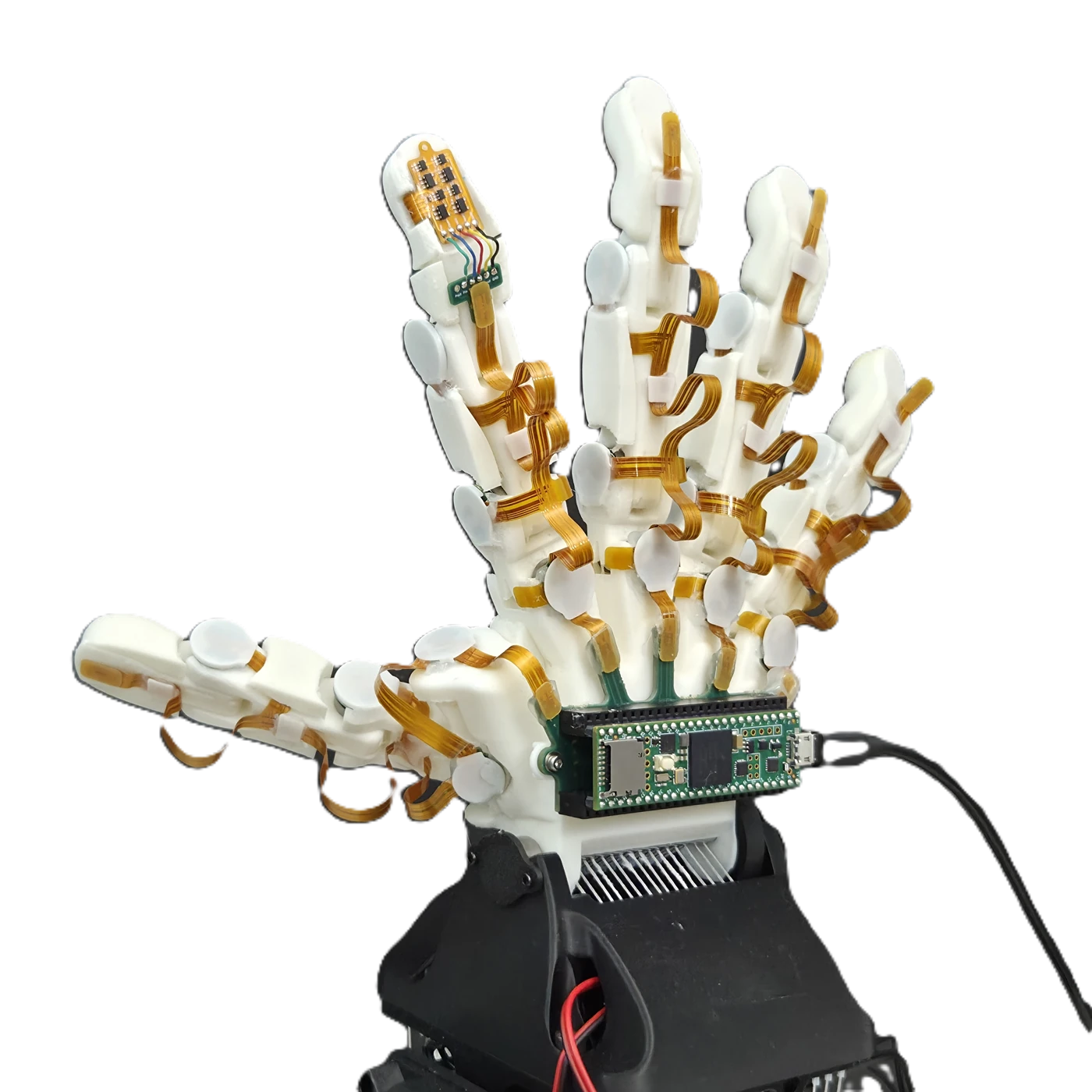
Implemented in the hand20 channels16 joint + 4 tactile sensing channels


IEEE ROBOTICS AND AUTOMATION LETTERS · EARLY ACCESS 2026
1 Soft Robotics Lab, IRIS, D-MAVT, ETH Zurich 2 Integrated Systems Laboratory, ETH Zurich
Joint and tactile feedback, connected through one compact readout architecture.
Integrate different analog-output sensors through one centralized ADC.
Extend sensor chains and select finger-level branches with dedicated input pulses.
Set the full-scan rate through the clock. ADC conversion time chiefly limits the maximum rate.
REPEATED INTERACTION
Repeated contact reveals the difference between directly measured joint angles and motor-based estimates.
Explore the experiments ↓THE IDEA
Dexterous hands need to know both how they move and what they touch.
Adding sensors inside a tendon-driven hand competes with tendons and joints for space. This work centralizes analog-to-digital conversion and uses a shift register to select sensor outputs in sequence over a shared analog line.
Each sensing unit adds only a D flip-flop and an analog switch to its base sensor. The same readout supports different analog-output sensors, serial expansion, and selective access to finger-level branches.
Dexterous robotic hands require high-speed multimodal sensing across many degrees of freedom, yet existing readout architectures often impose trade-offs between sensor count, wiring complexity, and sampling bandwidth. This paper presents a scalable analog sensor readout architecture based on a serial-in parallel-out (SIPO) shift-register principle. The proposed architecture supports versatile integration of heterogeneous analog-output sensors, scalable expansion using only three signal lines between sensor modules, and fast, configurable sampling. We validate the approach on a tendon-driven robotic hand integrating 16 joint sensor modules and one four-channel tactile sensor module, enabling acquisition of 20 sensor channels at a full-scan rate of 1 kHz, with stable operation up to 1.5 kHz. Joint sensor characterization showed a maximum slope absolute percentage error (APE) of 0.446% and sub-degree estimation error, indicating that the proposed readout system preserves sensing performance. For tactile sensing, LSTM-based models enabled real-time force estimation and contact-location classification at 1 kHz. System-level experiments showed that the joint sensors provided more accurate feedback than motor-based estimation during interaction. Closed-loop experiments further demonstrated improved joint trajectory tracking using joint-sensor feedback and force-controlled object pinching using tactile feedback. The proposed architecture offers a practical path toward sensorized robotic hands for dexterous manipulation.
THE ARCHITECTURE
A serial-in parallel-out shift register moves the selection pulse along the chain. Each selected switch connects its sensor to the shared ADC.
LIVE SIGNAL WALKTHROUGH
Slowed, idealized illustration of the readout principle. T is one clock period. Analog voltage is illustrative, not experimental data. Vout is drawn only while this sensor is connected. Blank intervals indicate disconnection, not zero volts. The dashed line beside the switch indicates its control linkage. ADC reading is illustrated after the falling clock edge. Power and ground remain connected.
FROM ONE UNIT TO A SENSOR CHAIN
Follow one selection pulse along the chain. Each unit connects its sensor to the shared analog line for one clock period.
A rising edge shifts the pulse to the next flip-flop. Only the selected unit closes its switch.
Vout follows that unit’s sensor voltage. Dots mark ADC reads after each falling clock edge.
A new input pulse starts the next scan. At a fixed clock rate, N units need N clock periods per full scan.
Idealized timing and example voltages, not oscilloscope measurements. Switching transients, ADC conversion time and electrical settling are omitted. Power and ground connections are omitted from the drawing. Blank Vout before the first selection means disconnected, not zero volts. Voltage changes apply only to newly drawn time; rewinding preserves recorded values. The PC receives one value per ADC sample, in unit order; -- means not yet received. It keeps the latest two scans across plot loops. Reset or changing the unit count clears the received data. Each plot loop starts a fresh waveform recording. With one unit, Q1 stays high between repeated scans because each rising edge captures a new input pulse.
HARDWARE & INTEGRATION
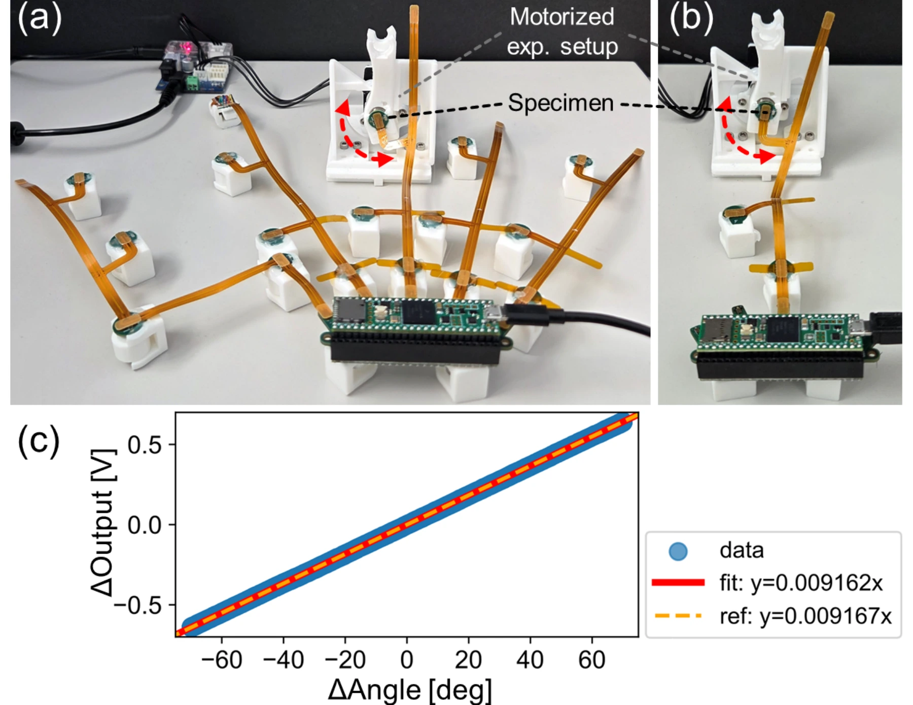
Sixteen joint sensor modules and one four-channel tactile module connect through flexible interconnects to a shared readout.

Flexible interconnects route the joint and tactile sensor signals to the wrist-mounted interface board.

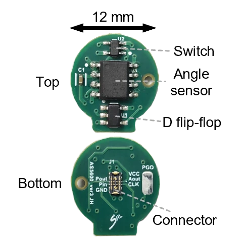
An AS5600 magnetic rotary sensor measures the joint angle locally.
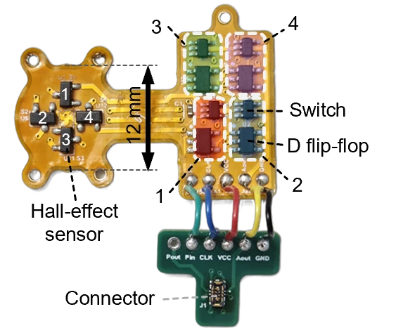
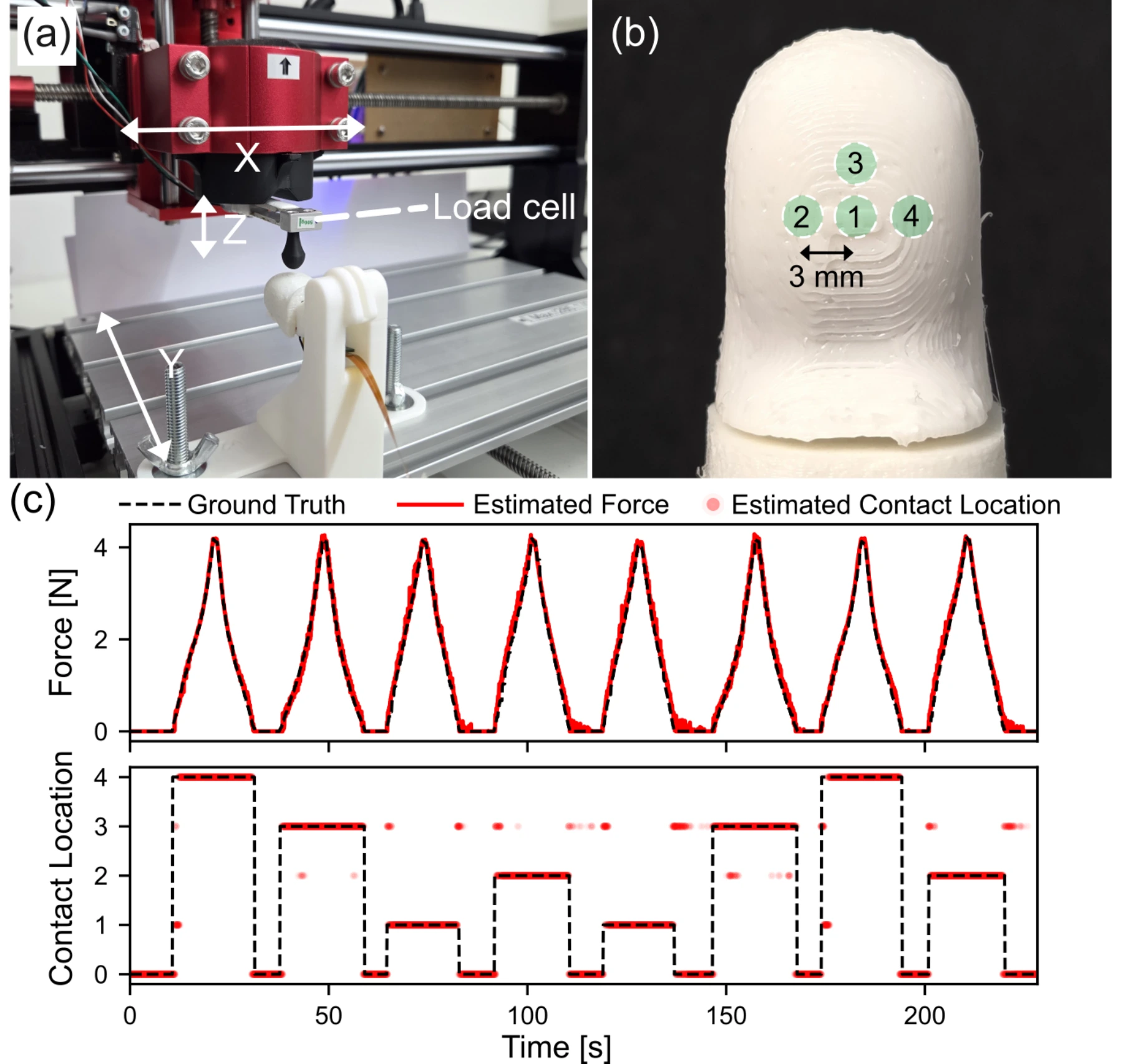
Four Hall-effect sensors feed separate LSTM models for force estimation and contact-location classification.
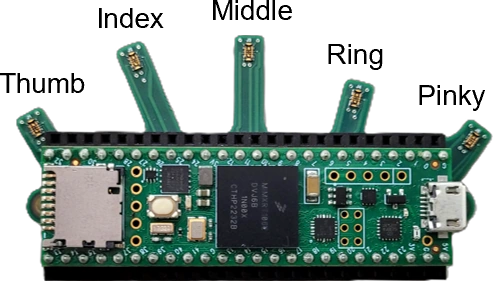
A Teensy 4.1 selects sensor outputs, samples their voltages and sends the readings to a PC.
The MCU supplies a shared clock and a separate selection pulse for each finger branch. Within a branch, the pulse advances one sensing unit per clock cycle, connecting its output to the shared ADC. The MCU sends the readings to the PC over USB serial for processing in ROS 2.

EXPERIMENTAL RESULTS
Validation spans sensor characterization, physical interaction, joint trajectory tracking, and tactile-based pinching.
0.233–0.368°
Range of mean RMSE across seven conditions, with five trials per condition, using the reference sensor slope (Table I).
0.125 N
Entire test set (Section III-B). For force above 0.05 N, RMSE is 0.148 N.
93.4%
Test-set accuracy over five classes: no contact and four predefined contact locations (Section III-B).
Joint sensing and fingertip force estimation, in motion.
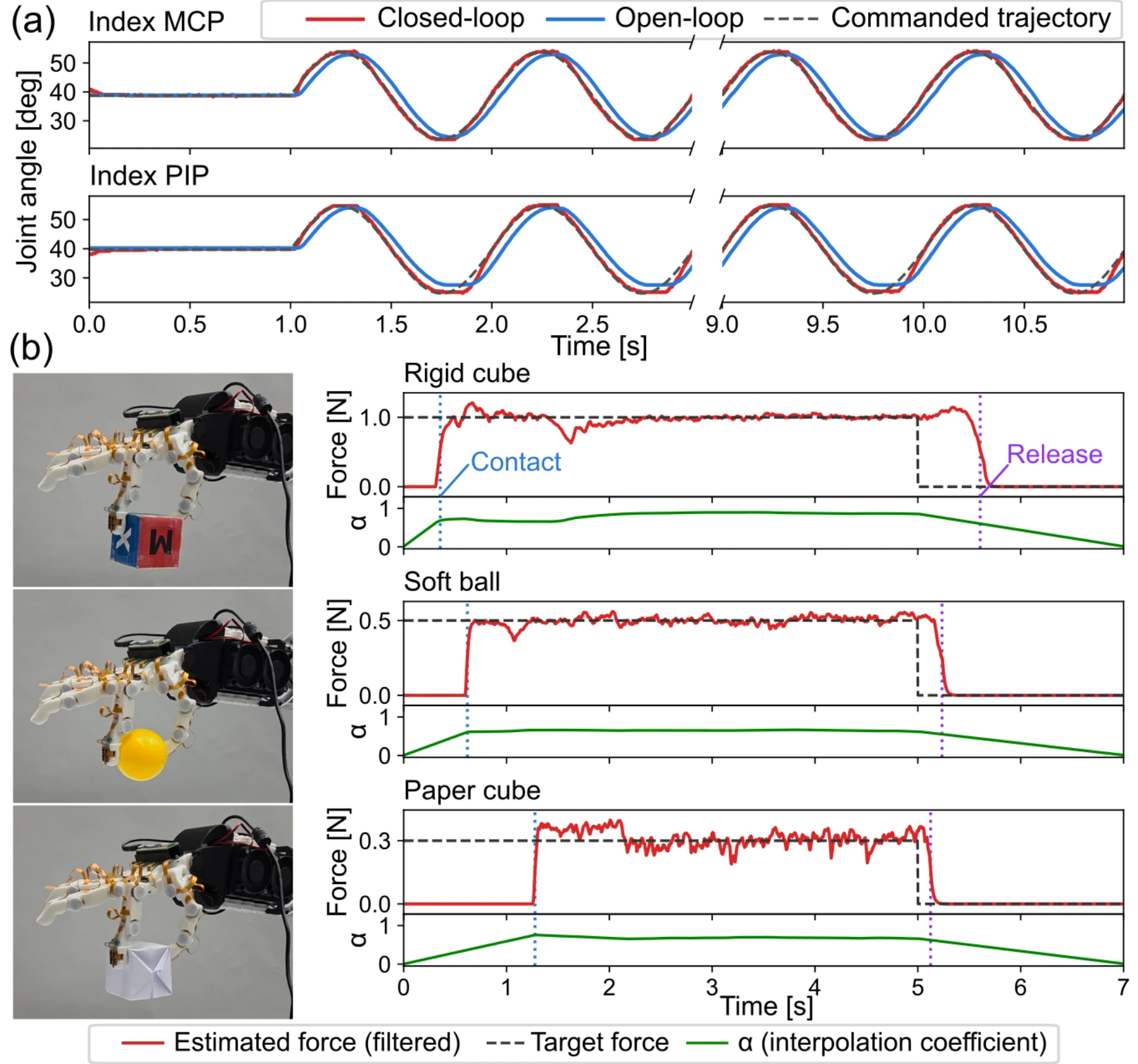
Tendon compliance and transmission uncertainty can make motor-based joint estimation less reliable during physical interaction. Dedicated joint sensors tracked vision-based ground truth more closely, even after additional calibration of the motor-based estimates.
| Joint | Joint sensor (ours) | Motor-based |
|---|---|---|
| MCP | 0.387° | 2.343° |
| PIP | 0.598° | 2.599° |
Sensor feedback reduced mean tracking RMSE across 16 joints from 3.13° to 0.92° in 1 Hz sinusoidal trajectory experiments. Both controllers ran at 200 Hz.
Mean (standard deviation): open loop 3.13° (0.39°); closed loop 0.92° (0.24°). Tracking error was measured against joint-sensor readings.
A rigid cube, a soft ball, and a paper cube: tactile feedback regulates pinching force across objects with different compliance.
Steady-state force tracking RMSE: 0.038 N, 0.032 N, and 0.055 N, respectively, measured between the unfiltered force estimates and target forces from 3.0 to 4.8 s.
FULL RESEARCH FILM
Research film · 3 min 21 s
Hardware integration, multiplexed sensing, experimental validation, and feedback control.
PAPER & RESOURCES
Published October 8, 2026 · IEEE Robotics and Automation Letters · Early Access
DOI: 10.1109/LRA.2026.3741779 ↗
@article{kim2026sensorreadout,
  title = {High-Speed, Scalable Sensor Readout for Dexterous
           Robotic Hands via Shift-Register Multiplexing},
  author = {Kim, Jaehoon and An, Boshi and Christoforidis, Lazaros
            and Papadakis, Michail and Kartsch, Victor
            and Katzschmann, Robert K.},
  journal = {IEEE Robotics and Automation Letters},
  year = {2026},
  pages = {1--8},
  doi = {10.1109/LRA.2026.3741779},
  url = {https://ieeexplore.ieee.org/document/11726871},
  note = {Early Access}
}
IEEE Early Access citation · published October 8, 2026. Volume and issue are not yet assigned.
This work was supported by SNSF Project Grant #200021_215489. Michail Papadakis received scholarship support from the Eugenides Foundation.